


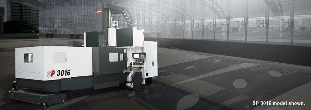

SP-3016 - Bridge Type Vertical Machining Center
Location:Boca Raton, FL
Description
X-axis travel : 82.7" / 120.5" / 157.5"
Y-axis travel : 62.9"
Z-axis travel : 29.9"
Dist. between columns : 66.9"
Table size ( X-direction ) : 90.9" / 128.3" / 165.3"
Table size ( Y-direction ) : 58.9"
Table load capacity : 17,600 / 22,000 / 26,400 lb
Spindle speed : 6,000 rpm
Spindle Power : 22 / 26 kW ( 30 / 35 HP )
( cont. / 30 min. )
Tool magazine capacity : 32 T ( 60 / 90 / 120 Opt. )
Standard Accessories
Spindle cooling system
Fully enclosed splash guard w/o roof
Coolant system with pump and tank
Twin screw type chip conveyor
Caterpillar type chip conveyor and bucket
Foundation bolt kit
Tool box
Alarm light
Water gun
Automatic power off system
Optinal Accessories
Spindle:
Spindle taper : CAT50
Y travel extension :
2,500 / 3,200 / 4,000 mm ( 98.4" / 125.9" / 157.5" )
Z travel extension :
1,000 / 1,200 / 1,400 mm ( 39.3" / 47.2" / 35.1" )
Column extension :
200 / 300 / 400 / 500 mm ( 7.87" / 11.81" / 15.74 / 19.68" )
Milling head ( Manual ) :
35° / 90° / Extension / Universal Head
Milling head ( Automatic ) :
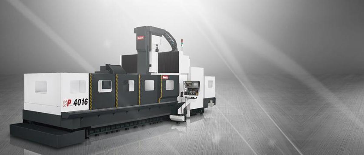
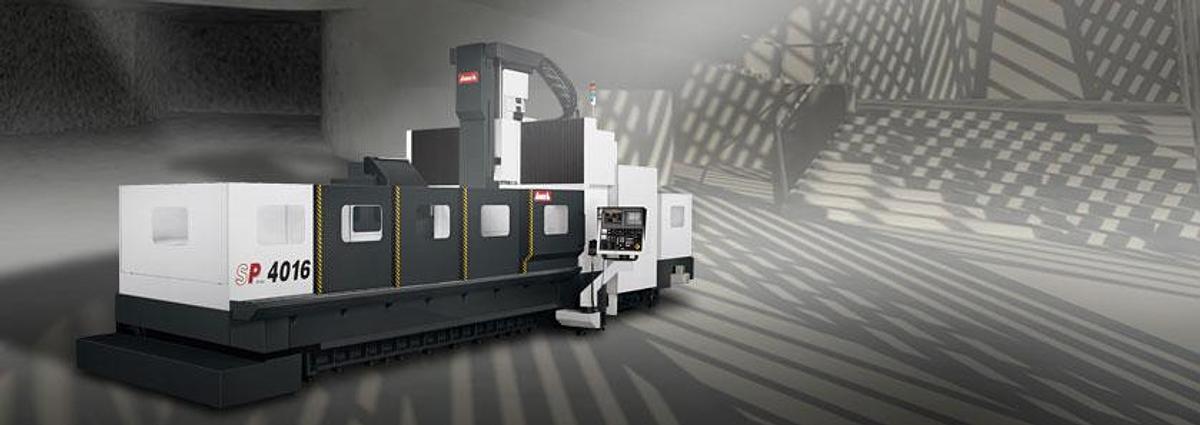
Ultra Performance Bridge Type Machining Center
Representing YAMA SEIKI’s “The royal family of bridge machines” of mature manufacturing abilities and advanced technology skills, the SP series bridge type vertical machining centers combine strong spindle power and high rigidity structure along with high quality automation equipments and full product line to provide you with high efficiency, high productivity machining strategies; it can be broadly applied in the automotive, precision mold, aerospace and energy industries., etc.
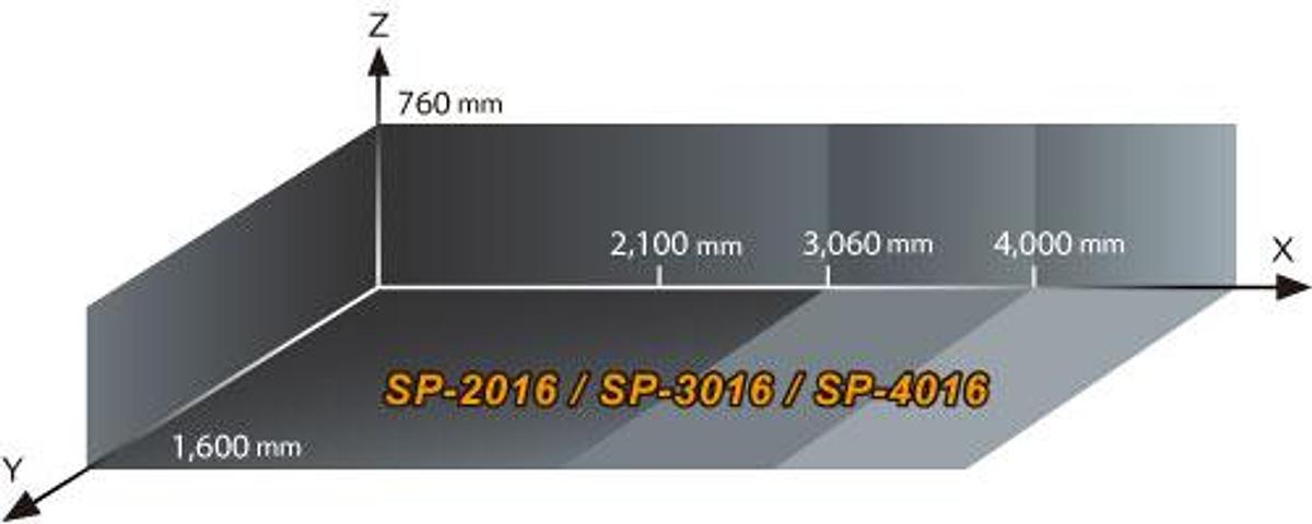
SP series Product Map
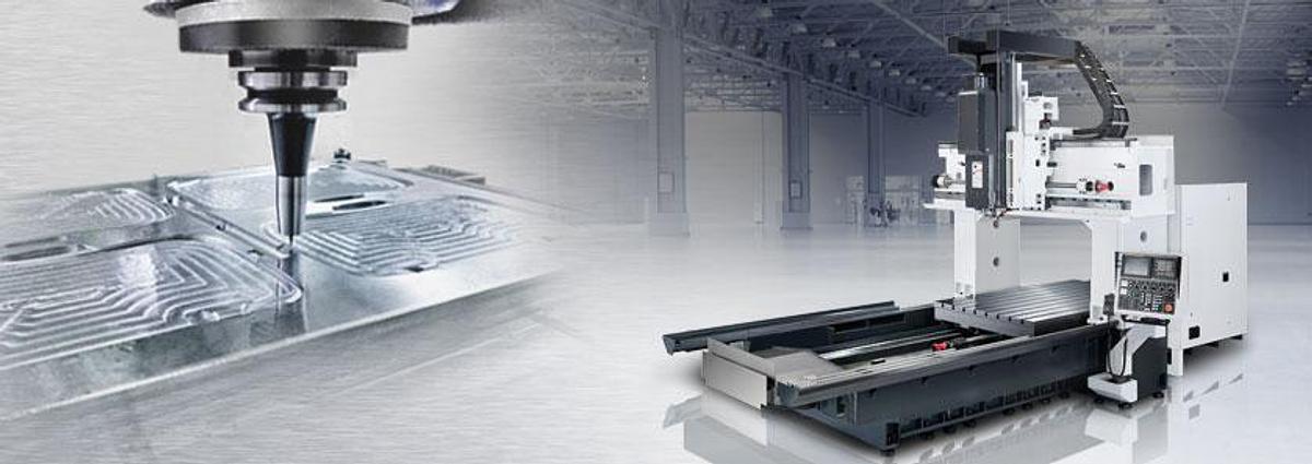
Thanks to our advanced developing skills and strict assembly process, gives the SP series ultra performance bridge type vertical machining center optimum rigidity, accuracy and efficiency.
The modular spindle design provides cutting flexibility for various working conditions.
High rigidity roller type linear guide ways on the X, Y axes offer heavy-duty cutting, fast movement and low abrasion capabilities.
The Z-axis is adopted with high rigidity box way which is hardened and precisely ground suitable for heavy-duty cutting conditions.( Opt. : The Z-axis can be adopted with roller type linear guide ways if equipped with high speed direct driven spindle. )
High Rigidity Structure
One-piece bridge and base casting structure with hand scraped contact surfaces ensure optimum assembly precision, structural rigidity and load balancing.
Rib reinforced working table restrains vibration while increasing machining stability.
The Finite Element Method ( FEM ) analysis provides optimum machine design and light-weighted structure advantages while ensuring best machine rigidity.
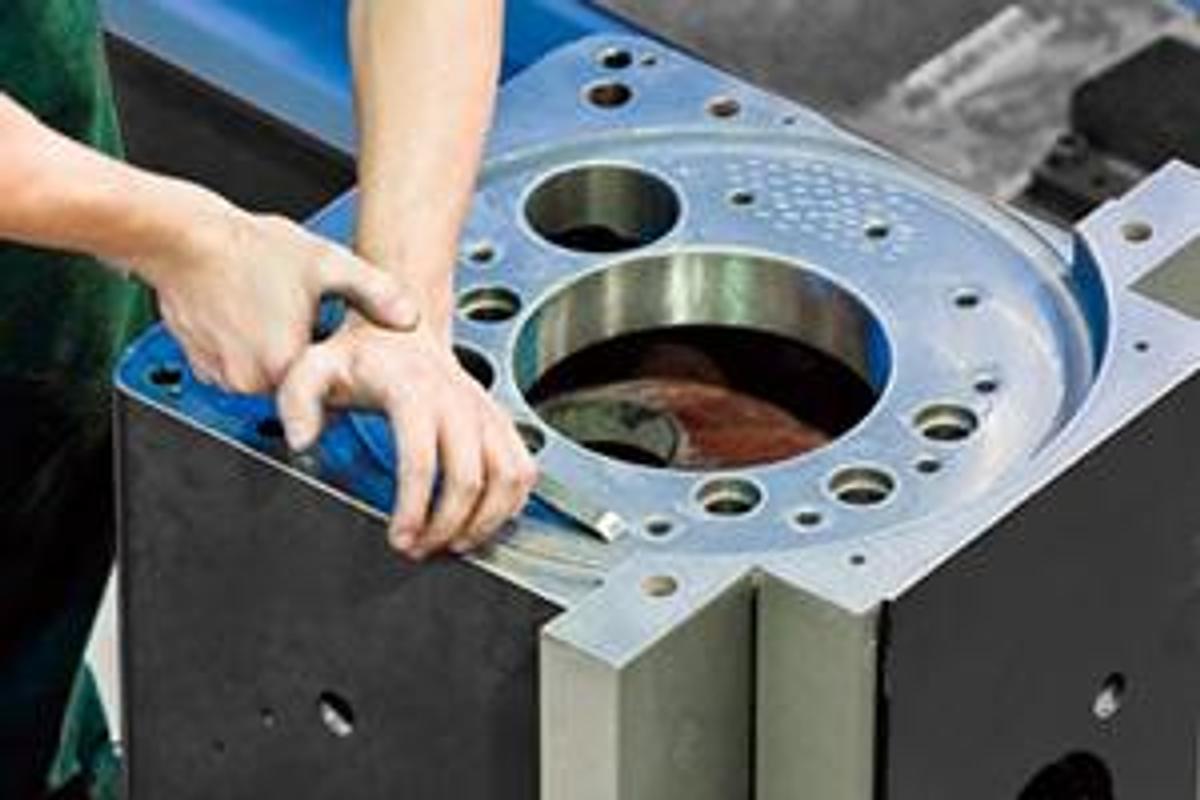
Precision Hand Scraping
All contact surfaces are precisely hand scraped to ensure maximum precision and rigidity.
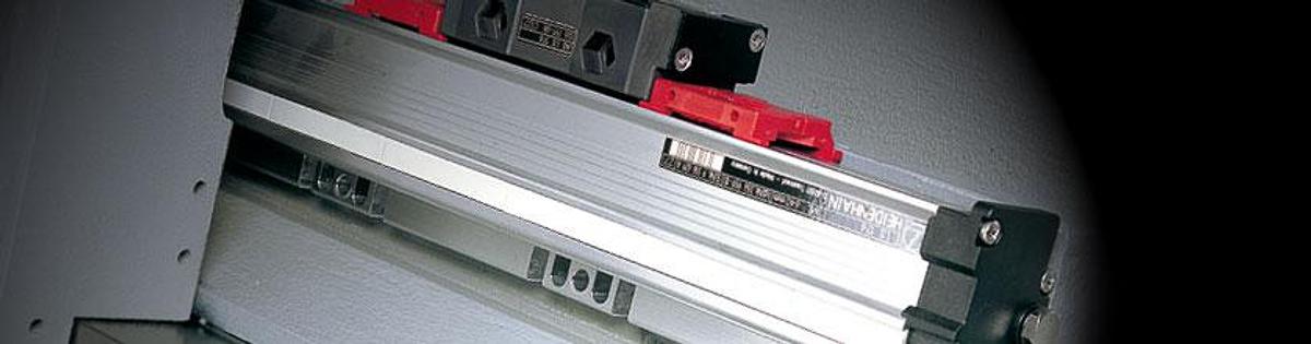
Precision Feedback System
The semi-closed loop circuit system which the ball screw end is directly connected to the encoder ensures high positioning accuracy.
Axial Torque Clutch
Three axes ball screws are equipped with mechanical torque clutches to minimize damages due to over load issues or crash.
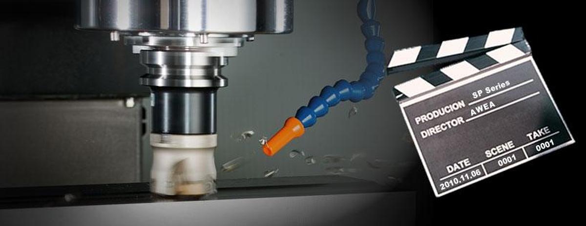
Optimum Spindle System
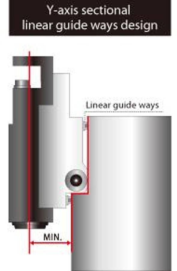
lnner-rail embraced structure provides high rigidity and gains good stress flow which minimizes over hang and vibration issues. The Y-axis roller type linear guide ways offset from each other increases structural rigidity reduces distance between spindle to cross beam enhances overall cutting performance.
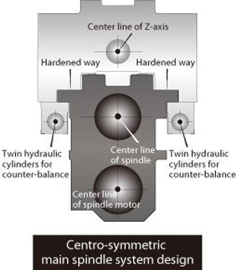
Unique head design which the main spindle, spindle motor, ball screw and hydraulic counter weight cylinders are symmetrically placed. Hereby preventing thermal distortion and minimizing deflection. Assuring accuracy and heavy cutting capability.
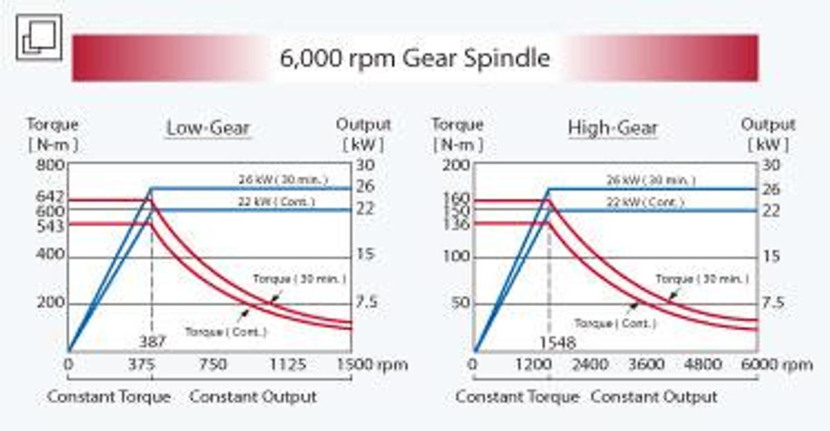
2-speed super heavy-duty gear box.
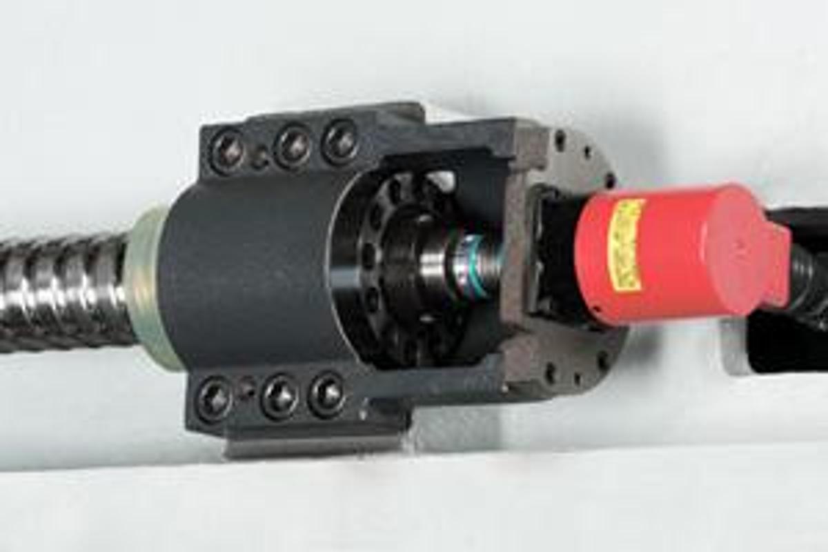
Floating type hydraulic tool release device eliminates pressure on the spindle bearing when releasing a tool.
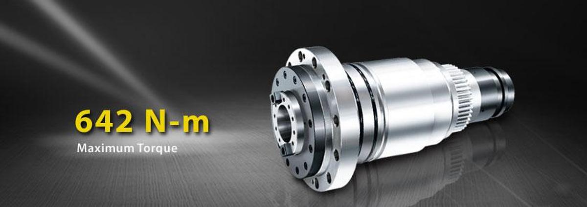
6,000 rpm high torque spindle is equipped with powerful 26 kW motor delivers maximum torque output of 642 Nm at 387 rpm.
6,000 rpm Gear Spindle
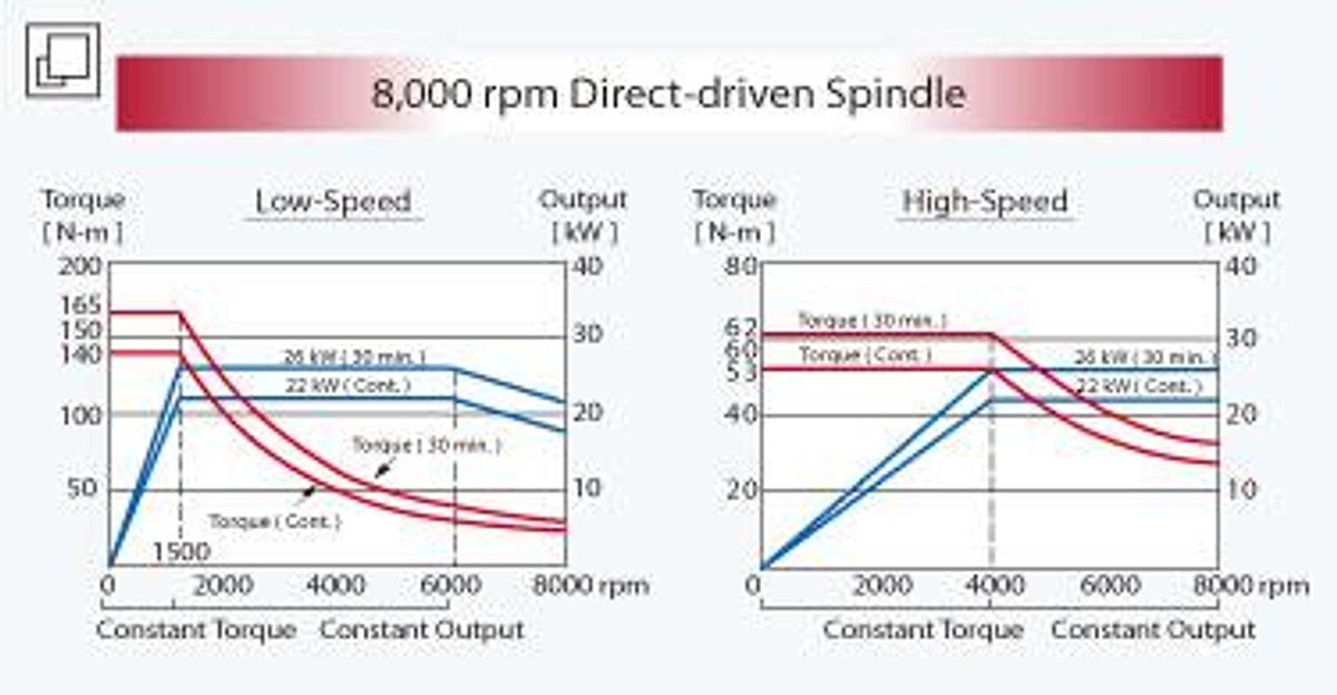
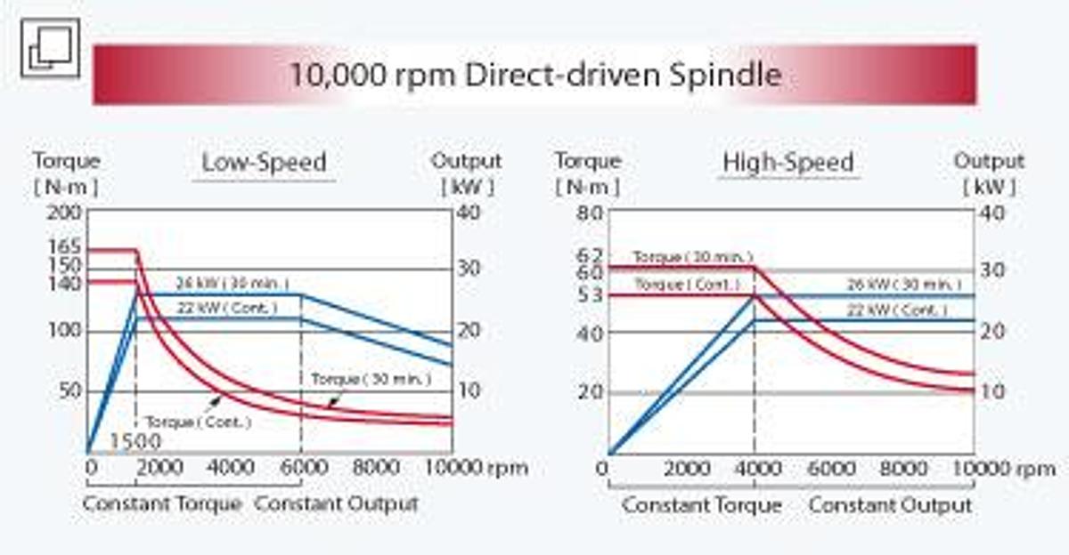
Direct-drive spindle efficiently separates the heat generated from the motor, which reduces deformation, therefore, increasing machining accuracy.
Floating type hydraulic tool release device eliminates pressure on the spindle bearing when releasing a tool.
8,000 rpm and 10,000 rpm are available, which provides maximum 165 Nm torque output at 1,500 rpm to meet with various high speed working conditions.
8,000 rpm Direct-drive Spindle
10,000 rpm Direct-drive Spindle
NC Intelligence
Multiple Functions Status Display
Trouble Shooting
When the alarm appears, the program will display the breakdown cause and a troubleshooting procedure. Users can easily troubleshoot minor problems to save machine shutdown time.
Circular Work Piece Measurement
The circular work piece program can calculate the center coordinate of a work piece by measuring point A, B and C coordinates.
Rectangular work piece measurement
The rectangular work piece program can calculate the center coordinate and the slant angle of a work piece by measuring point A, B, C, D and E coordinates; the calculated center coordinate can be inputted into the work piece coordinate program( G54~G59 ).
Manual Tool Length Measurement
After manually measuring the tool length, the controller will automatically calculate the tool tip position and input the data into the tool length offset table.
Adaptive feed control
Adaptive feed control is capable of real-time monitoring the spindle load to control the axial feed rate which effectively extends tool life, shortens rough cutting time, and detects abnormal cutting conditions.
CNC parameter optimization
From rough cutting to fine finishing, the operator can select various cutting modes based on the working condition, and then set the allowable error and work piece weight to obtain the optimum parameter.
Specifications
| Manufacturer | Yama Seiki |
| Model | SP-3016 |
| Condition | New |
| X / Y / Z axes travels | 120.5" x 63.0" x 30.0" |
| Spindle nose to table top | 9.4" ~ 39.4" |
| Distance between columns | 66.9" |
| Spindle motor | 35 HP ( 30 min. ) |
| Spindle speed | 6,000 rpm |
| 列印此頁面 | SP-2016 | SP-3016 | SP-4016 |
| X-axis travel | 2,100 mm ( 82.7" ) | 3,060 mm ( 120.5" ) | 4,000 mm ( 157.4" ) |
| Y-axis travel | 1,600 mm ( 62.9" ) |
| Z-axis travel | 760 mm ( 29.9" ) |
| Dist. form spindle nose to table top | 240 ~ 1,000 mm ( 9.4"~ 39.3") |
| Dist. between columns | 1,700 mm ( 66.9" ) |
| Table size ( X direction ) | 2,310 mm ( 90.9" ) | 3,260 mm ( 128.3" ) | 4,200 mm ( 165.3" ) |
| Table size ( Y direction ) | 1,500 mm ( 59.1" ) |
| Table load capacity | 8,000 kg ( 17,600 lb ) | 10,000 kg ( 22,000 lb ) | 12,000 kg ( 26,400 lb ) |
| Spindle motor ( cont. / 30 min. ) | 22 / 26 kW ( 30 / 35 HP ) |
| Spindle taper | CAT50 |
| X-axis rapid feedrate | 20 m/min. ( 788 IPM ) | 20 m/min. ( 788 IPM ) | 15 m/min. ( 590 IPM ) |
| Y-axis rapid feedrate | 20 m/min. ( 788 IPM ) |
| Z-axis rapid feedrate | 15 m/min. ( 590 IPM ) |
| Cutting feedrate | 10 m / min. ( 393 IPM ) |
| Tool magazine capacity | 32 ( 60 / 90 / 120 Opt. ) |
| Max. tool diameter / adj. pocket empty | Ø 127 / 215 mm ( Ø 5.0" / 8.4" ) |
| Max. tool length ( from gauge line ) | 350 mm ( 13.7" ) |
| Max. tool weight | 20 kg ( 44 lb ) |
| Positioning accuracy( JIS B 6338 ) / Full Travel | ± 0.015 mm( ± 0.00059" ) |
| Positioning accuracy( VDI 3441 ) / Full Travel | P ≤ 0.020 mm( P ≤ 0.00078" ) | P ≤ 0.025 mm( P ≤ 0.00098" ) | P ≤ 0.030 mm( P ≤ 0.00118" ) |
| Repeatability( JIS B 6338 ) / Full Travel | ± 0.003 mm( ± 0.000118" ) |
| Repeatability( VDI 3441 ) / Full Travel | Ps ≤ 0.015 mm( Ps ≤ 0.00059" ) | Ps ≤ 0.020 mm( Ps ≤ 0.00078" ) | Ps ≤ 0.025 mm( Ps ≤ 0.00098" ) |
| Power requirement | 220 ± 10 % |
| Pneumatic pressure requirement ( min. ) | 5 ~ 8 kg / cm² ( 71 ~ 113.6 PSI ) |
| Hydraulic unit tank capacity , [ pump ] | 120 liter ( 31.5 gal ), [ 10 HP ] |
| Lubrication oil tank capacity | 6 liter ( 1.6 gal ) |
| Coolant tank capacity , [ pump ] | 420 liter ( 110 gal ) , [ 1.5 HP ] |
| Machine weight | 23,000 kg( 50,600 lb ) | 28,000 kg( 61,600 lb ) | 33,000 kg( 72,600 lb ) |