


HTP-5041 - Super Rigid Bridge Type Machining Center
Location:Boca Raton, FL
Description
X-axis travel : 157.4" ~ 275.5"
Y-axis travel : 98.4" ~ 188.9"
Z-axis travel : 39.3" / 47.2" / 55.1"
Dist. between columns : 106.2" / 137.7" / 169.2"
Table load capacity : 33,070 ~ 44,090 lb
Spindle speed : Gear Spindle 4,000 rpm
Spindle motor : 30 / 35 HP ( Opt. 40 / 50 )
( Cont. / 30 min. )
Spindle taper : BBT50 ( ISO 50 )
X-axis rapids feed rate : 590 / 393 / 295 IPM
Y-axis rapids feed rate : 472 / 393 IPM
Z-axis rapids feed rate : 472 / 393 IPM
Tool magazine capacity : 32 T ( Opt. 40 / 60 / 90 / 120 )
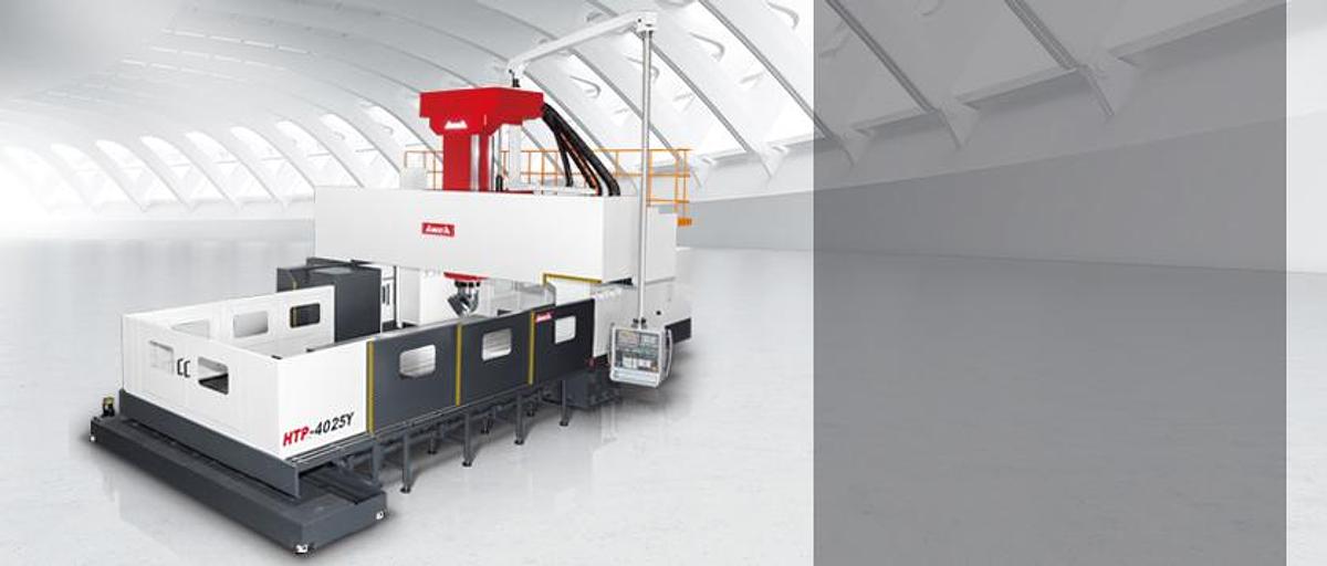
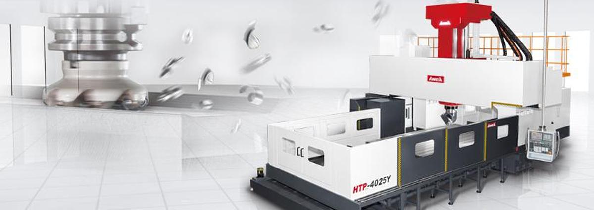
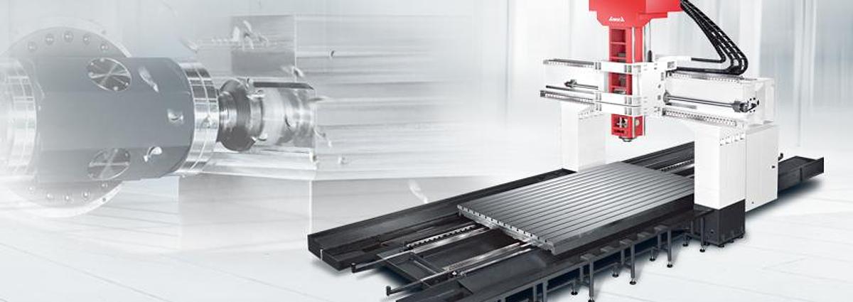
Super Rigid Bridge Type Machining Centers
The highly rigid HTP series is equipped with a high torque spindle for outstanding heavy cutting performance. It can easily increase the chip removal rate, reduce cycle time and complete tough material machining easily.
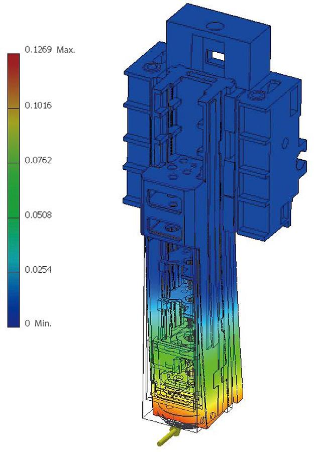
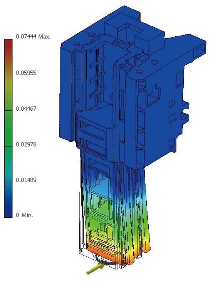
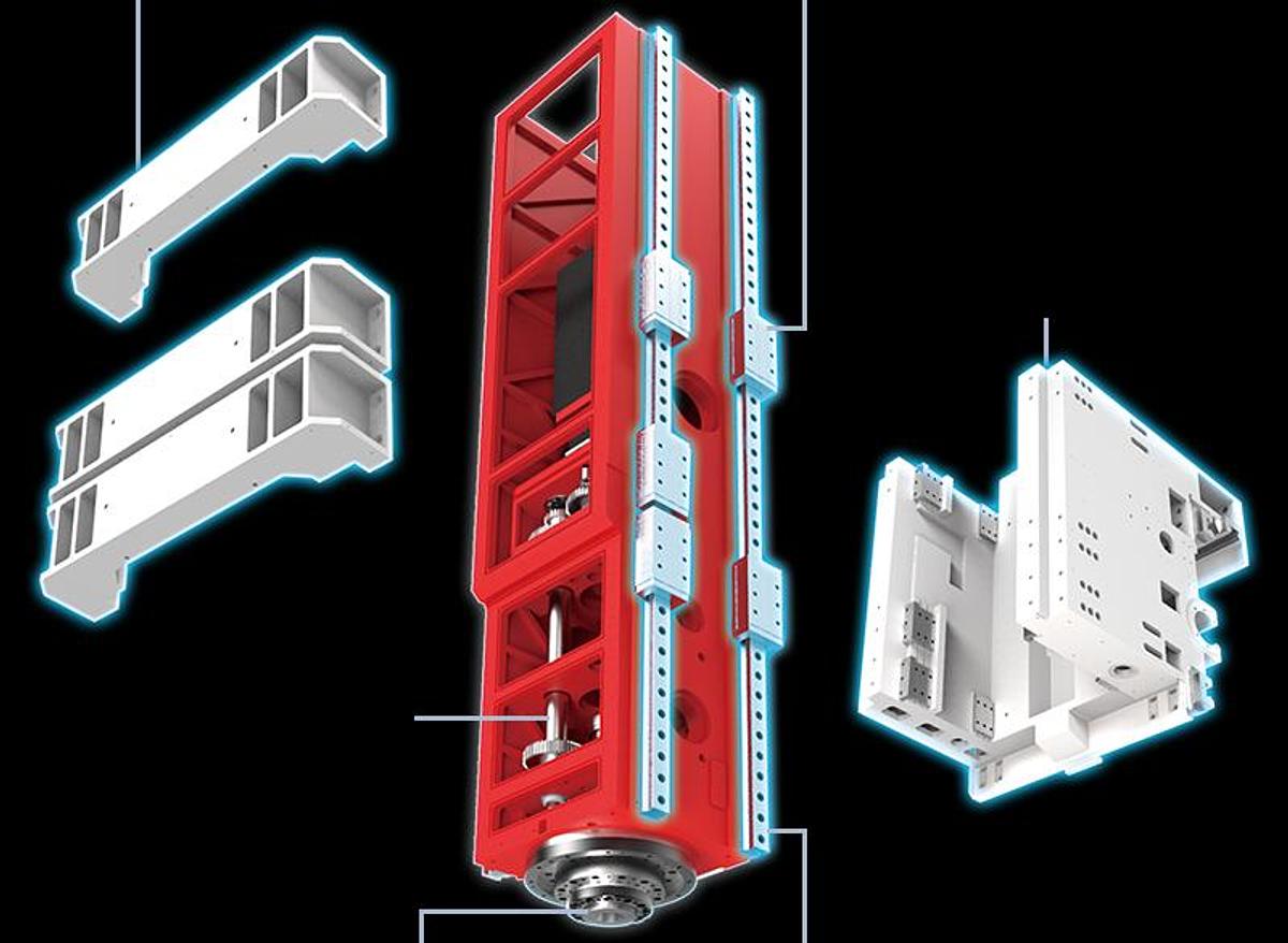
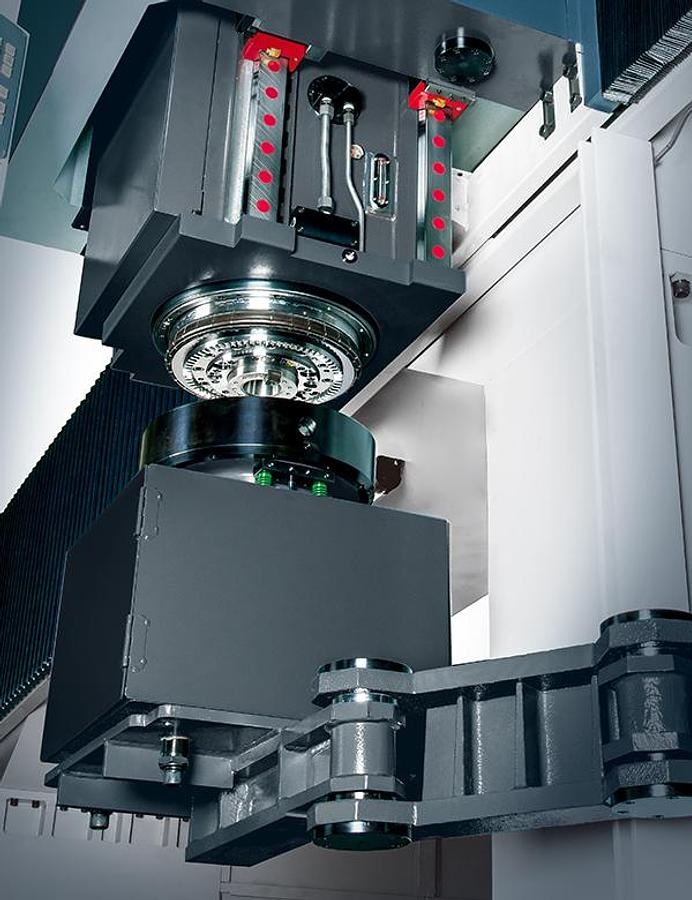
Strong spindle unit structure
The U-shaped saddle design with four linear guideways and ten sliding blocks supporting the Z-axis gives the spindle head firm support. Even with the Z-axis fully extended, the machine can still maintain excellent machining accuracy.
Load:5,000 N
Max. displacement 0.1269 mm
Load:5,000 N
Max. displacement 0.0744 mm
The rigidity of the head structure has been increased by
Best linear guideway arrangement
High quality 4 linear guideways supporting the X-axis and 3 guideways supporting the Y-axis allow the HTP series to easily surpass its competition in structural rigidity, table load and accuracy.
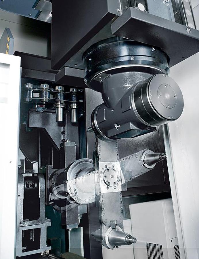
Flexible multi-face machining capability
An automatic head changer and a two positions ATC system are optional upgrades for improved multi-face machining.
A new generation of in-house made attachment heads is available now.
Exceptional capability of chip removal and cooling
Standard two coil type chip augers and a caterpillar type chip conveyor efficiently remove chips. The 1000L coolant tank effectively reduces cutting fluid heating, thus ensuring better machining accuracy.
Maximum Strength Construction
Finite Element Analysis
Employing the Finite Element Analysis (FEA) in the design process assures optimal rigidity and helps reducing the machine weight.
Precision hand scraping
The contact surfaces of column, base, cross beam and all sliding members are precision hand scraped to provide maximum assembly precision, structural rigidity, and optimal load distribution.
Roller type linear guide ways
Super rigid roller type linear guide ways on all three axes provide support for heavy-duty cutting and fast, low friction movements.
Precision feedback system
The semi-closed loop system with encoders directly connected to the ball screws ensures high repeatability and positioning accuracy.
4 guideways on base ( X-axis )
Compound 4 guideways design for maximum structural support and to reduced work table over hang.
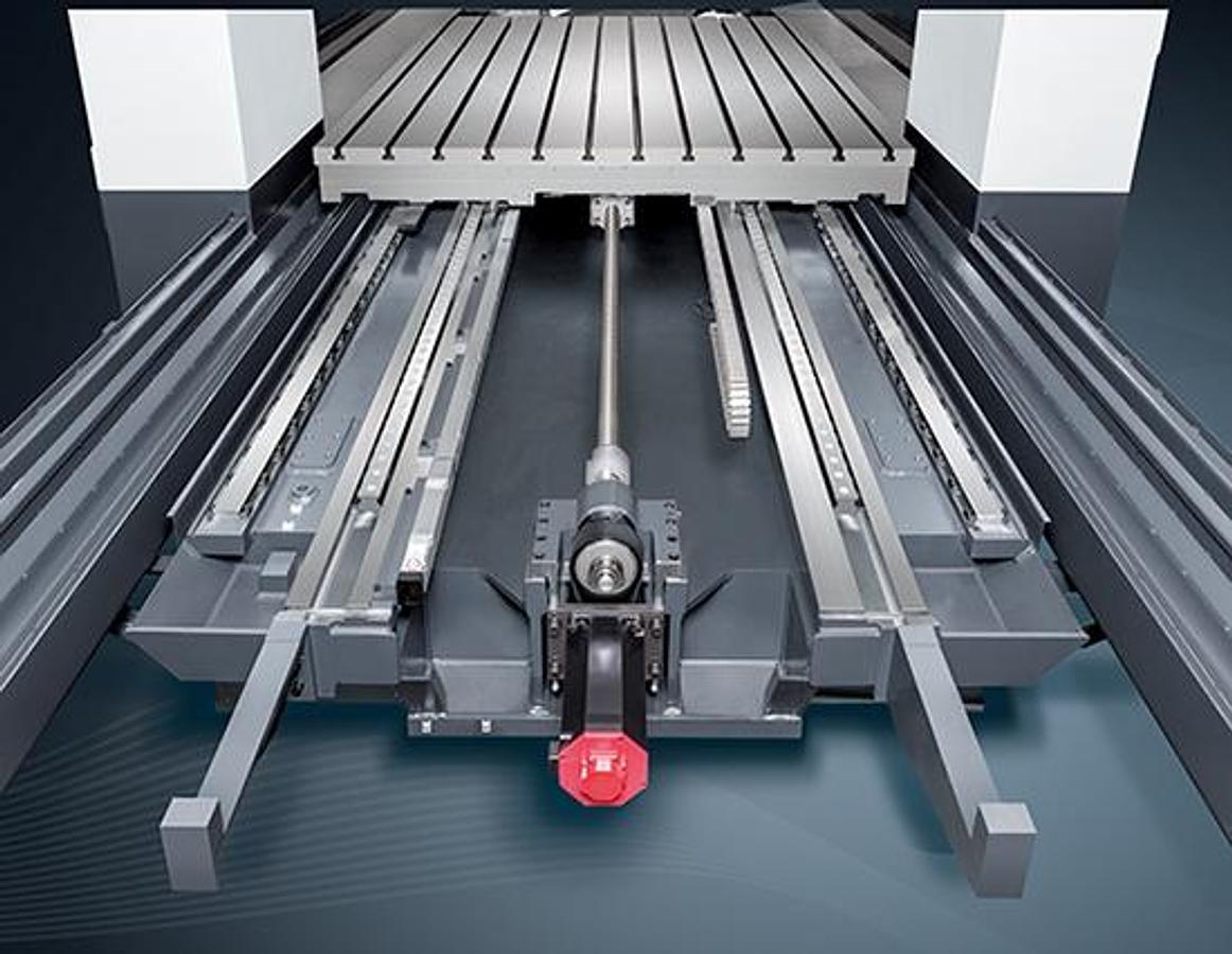
Symmetric support center-driven table
Wide span symmetrical center-driven X-axis design with the ball screw placed in the center of the table to provide high precision axial feeding.
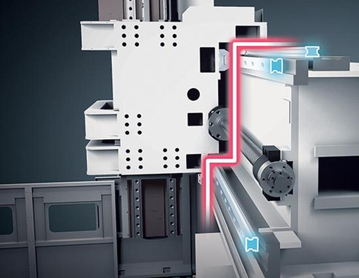
3 guideways Y-axis support
The stepped offset three guideways design of the Y-axis further enhance the rigidity. The new design effectively reduces the distortion due to headstock weight and significantly improves the rigidity for heavy cutting.
Closed loop counterbalance unit
The environmentally friendly closed loop hydraulic counterbalance system enables excellent dynamic movements.
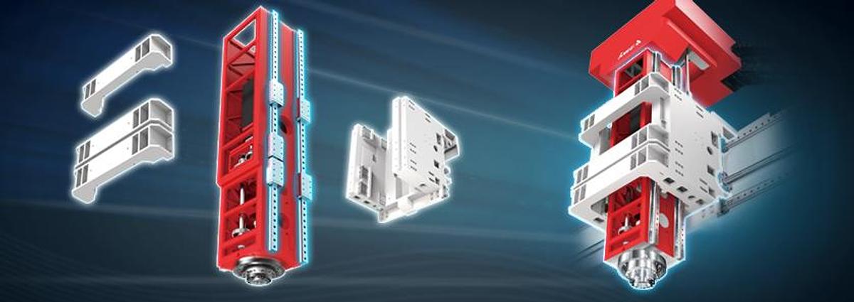
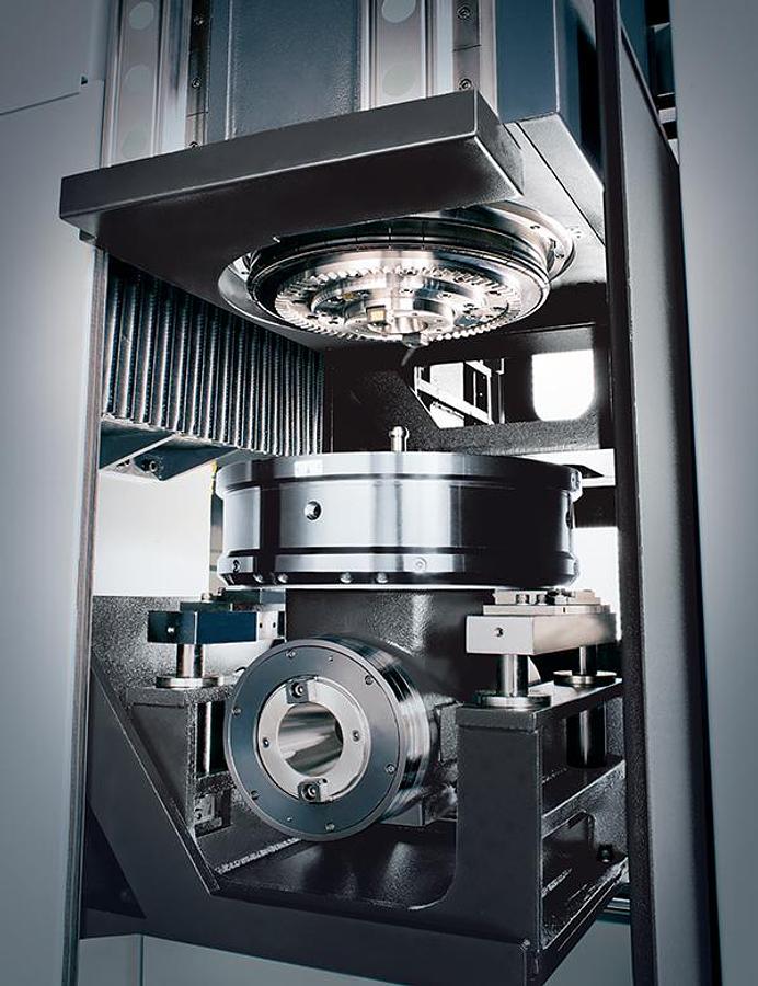
Super rigid spindle headstock structure
The saddle fixture provides additional support to prevent saddle deformation during heavy cutting.
The linear guideway is equipped with a built-in high resolution magnetic encoder for ensuring accurate positioning.
The newly designed U-shaped saddle is cast in one piece with strong ribbing to provide low weight, highly rigid support for the headstock that easily outperforms traditional designs.
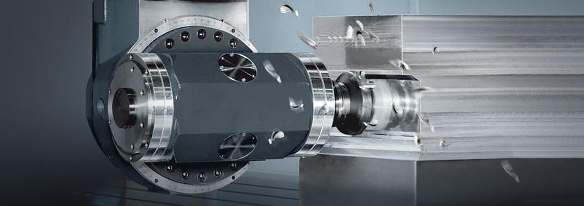
The gear head spindle is equipped with a newly designed short, highly rigid transmission shaft, enabling efficient power transmission suitable for heavy cutting.
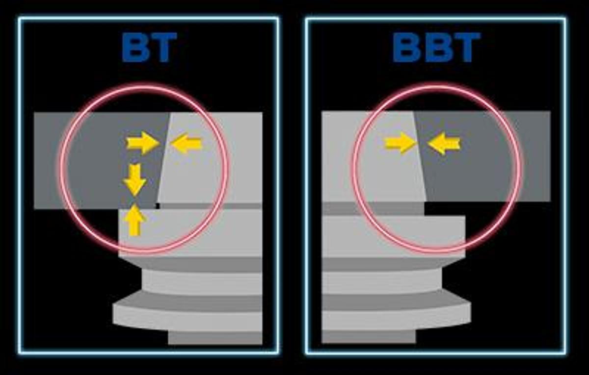
The BBT dual contact spindle ensures the spindle taper and face maintain contact with the tool holder to better meet the needs of heavy cutting.
There are two highly rigid roller type linear guideways on both sides of the headstock. They ensure the machine can still maintain excellent machining accuracy even when the Z-axis is fully extended.
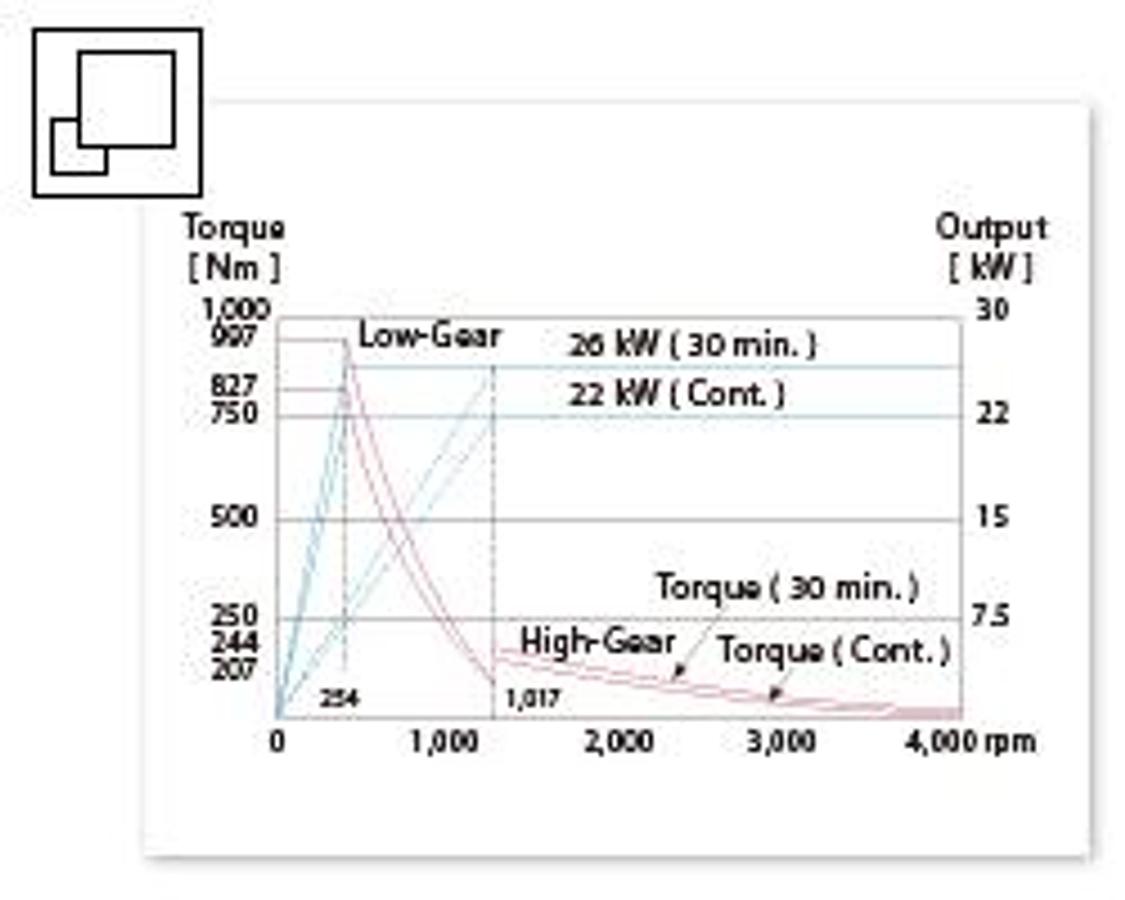
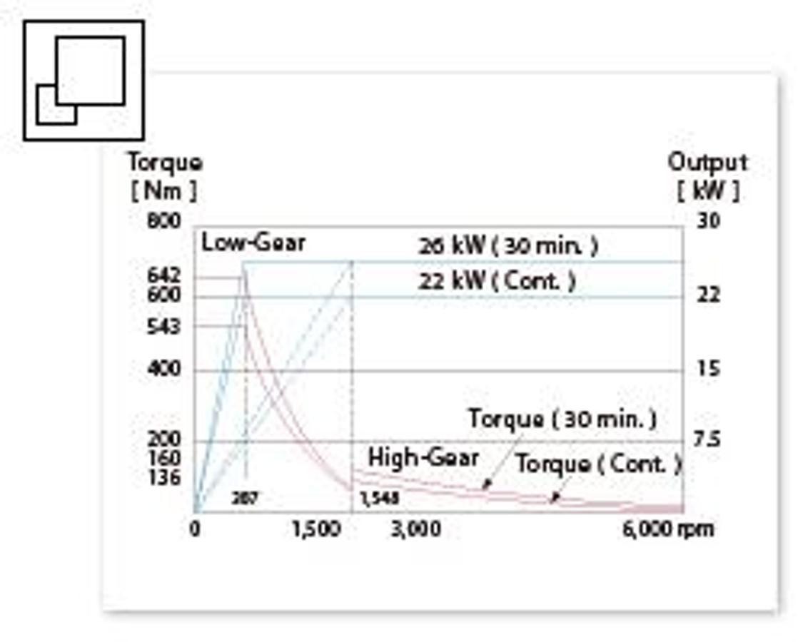
4,000 rpm Gear Spindle
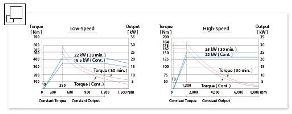
6,000 rpm Gear Spindle
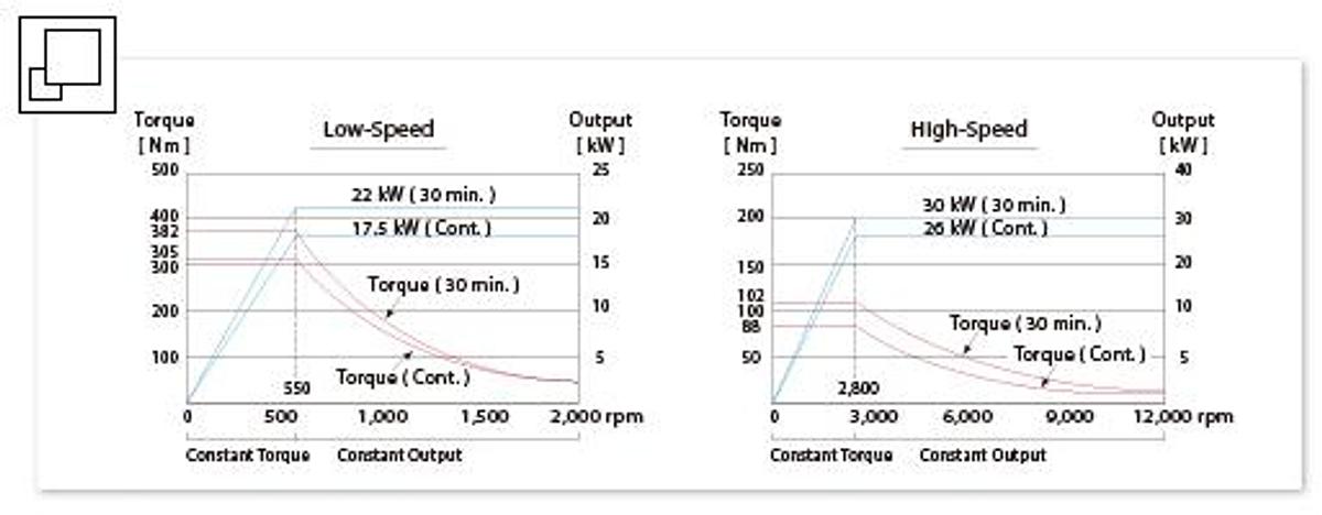
8,000 rpm Built-in Motorized Spindle
12,000 rpm Built-in Motorized Spindle
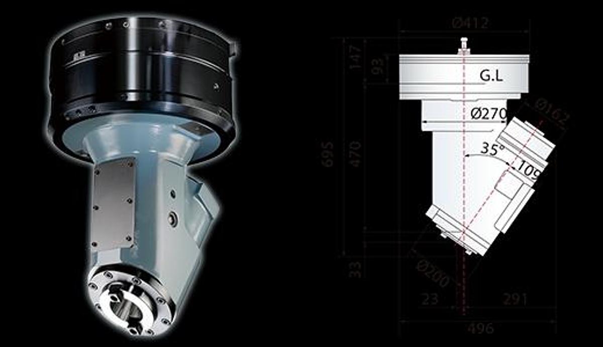
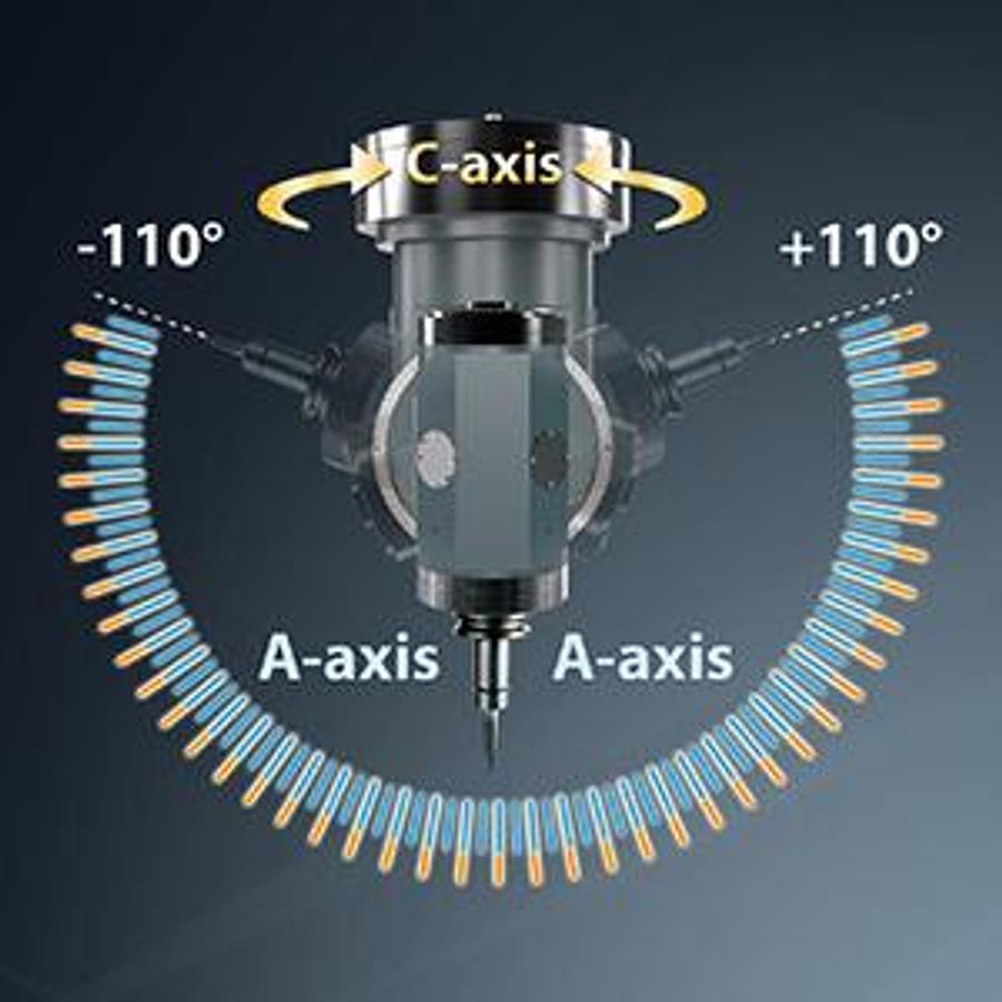
Automatic Milling Heads
The new generation milling heads designed and made by AWEA have comprehensive specifications and enhanced performance. Designed and built by AWEA for making seamless compatibility with the machines, enhancing reliability, performance, and accuracy all at the same time.
Higher rpm options and increased max.speed
Auto head changing and tool clamping available for the whole series
CTS available for the whole series
Automatic head clamp / tool clamp
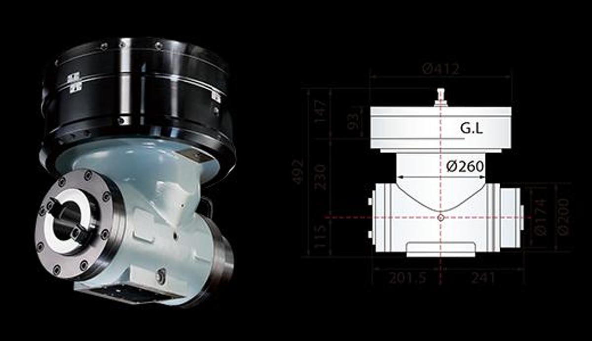
C-axis automatic:5° / 2.5°
Max. speed:3,000 / 4,500 rpm
Max. output:22 kW ( 30 HP )
Optional CTS
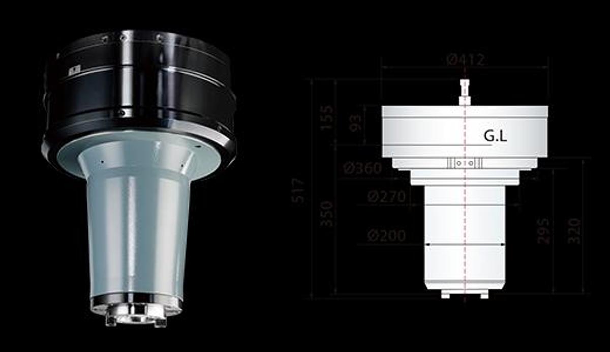
Automatic head clamp / tool clamp
C-axis automatic:5° / 2.5°
Max. speed:3,000 / 4,500 rpm
Max. output:22 kW ( 30 HP )
Optional CTS
Automatic head clamp / tool clamp
Max. speed:3,000 / 6,000 rpm
Max. output:22 kW ( 30 HP )
Optional CTS
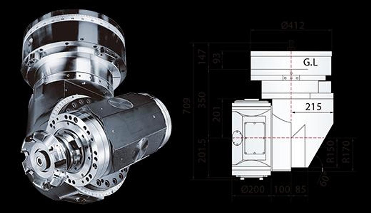
Automatic head clamp / tool clamp
Max. speed:3,000 / 4,500 rpm
Max. output:22 kW ( 30 HP )
Optional CTS
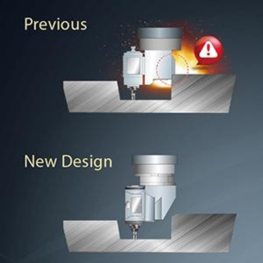
Compact layout design
The compact design reduces the inter ference between head and workpiece.
Finer degree indexing
A-axis degree indexing
⬛ 5° ⬛ 2.5° / 1°
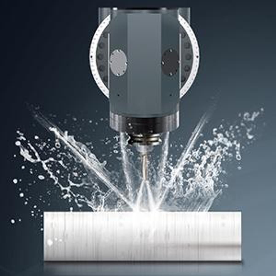
Better cooling and chip removal
Coolant nozzle around spindle
Coolant through spindle
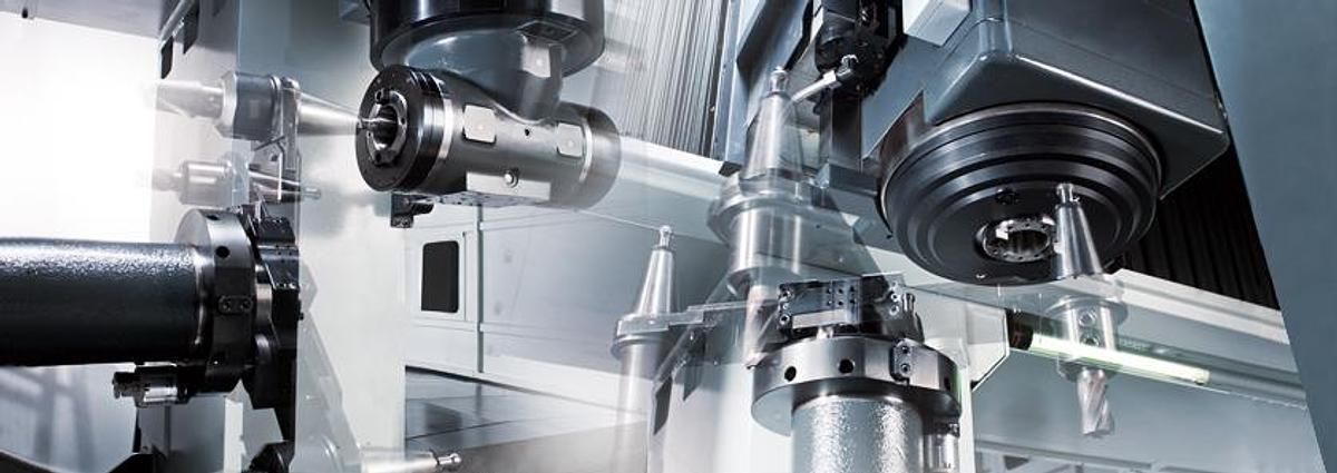
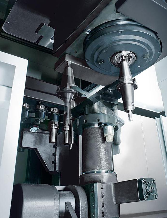
Multi-face Machining Capability
The optional automatic head changer and the vertical / horizontal ATC system enable the machine to perform highly efficient multi-face machining.
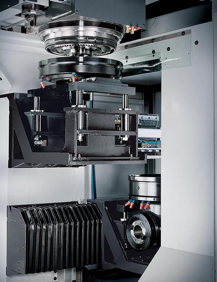
High efficiency automatic head storage magazine
• The two station automatic head storage system accommodates one cover and one 90° angle head. The system adopts linear guideways to achieve precise and fast head exchanges.
• The head changing system is attached to the column, thus reducing floor space.
• The magazine has an independent auto door that only opens during head exchanges to avoid chip and coolant contamination.
High reliability automatic vertical / horizontal ATC system
• The vertical / horizontal ATC system provides quick tool changes.
• Sensors and sequence scanning ensure safety and reliability.
• Standard 32 tools magazine; 40T / 60T / 90T / 120T magazine optional.
Automatic head storage compartment
Automatic head storage compartment
Swing type head storage
Vertical ATC
Horizontal ATC
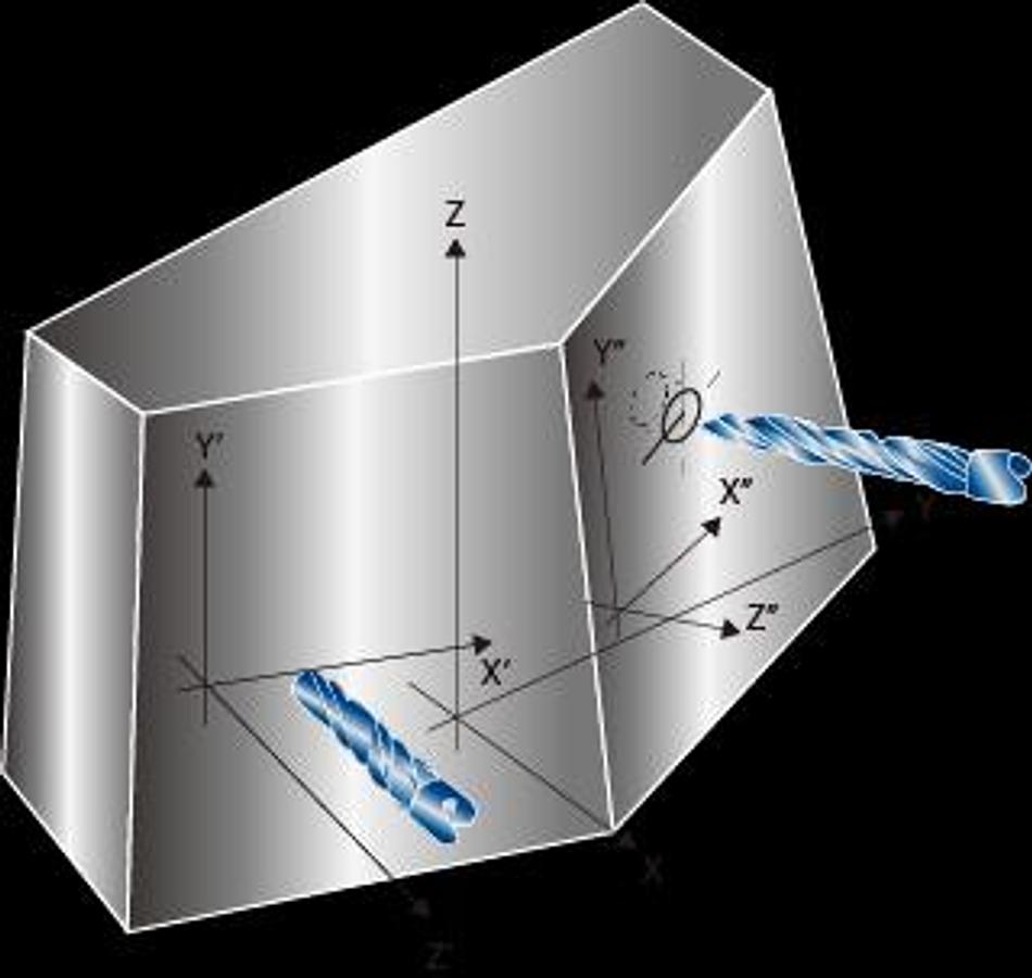
Multi-face 3D coordinate rotation
The standard 3D coordinate transform function can adjust the coordinate system to fit different machining orientations according to machining requirements. This helps to reduce cycle times.
Straight milling
Drilling
Slanted angle milling coordinate
( must order universal head )
slanted milling coordinate
Specifications
| Manufacturer | Yama Seiki |
| Model | HTP-5041 |
| Condition | New |
| X / Y / Z axes travel | 196.8" / 161.4" / 39.3" |
| Dist. between columns | 4,300 mm ( 169.2" ) |
| Table size ( X x Y ) | 4,020 x 3,000 mm( 158.2" x 118.1" ) | 5,020 x 3,000 mm( 197.6" x 118.1" ) | 6,020 x 3,000 mm( 237.0" x 118.1" ) | 7,020 x 3,000 mm( 276.3" x 118.1" ) |
| Table load capacity | 15,000 kg( 33.070 lb ) | 18,000 kg( 39,680 lb ) | 20,000 kg( 44,090 lb ) | 20,000 kg( 44,090 lb ) |
| Spindle speed | Gear Spindle 4,000 rpm |
| Spindle motor ( Cont. /30min.) | 30 / 35 HP( 40 / 50 Opt.) |
| Tool magazine capacity | 32 T ( Opt. 40 / 60 / 90 / 120 ) |
| Print this page | HTP-4041 | HTP-5041 | HTP-6041 | HTP-7041 |
| X-axis travel | 4,000 mm ( 157.4" ) | 5,000 mm ( 196.8" ) | 6,000 mm ( 236.2" ) | 7,000 mm ( 275.5" ) |
| Y-axis travel | 4,100 mm ( Opt. 4,800 )[ 161.4" ( Opt. 188.9" ) ] |
| Z-axis travel | 1,000 mm ( Opt. 1,200 / 1,400 )[ 39.3" ( Opt. 47.2" / 55.1" ) ] |
| Dist. from spindle nose to table top | 200 ~ 1,200 mm ( Opt. 200 ~ 1,400 / 200 ~ 1,600 )[ 7.8" ~ 47.2" ( Opt. 7.8" ~ 55.1" / 7.8" ~ 62.9" )] |
| Spindle taper | BBT50 ( ISO 50 ) |
| Spindle motor ( Cont. / 30 min. ) | 22 / 26 kW ( Opt. 30 / 37 )[ 30 / 35 HP ( Opt. 40 / 50 ) ] |
| X-axis rapids feed rate | 15 m/min.( 590 IPM ) | 10 m/min.( 393 IPM ) | 7.5 m/min.( 295 IPM ) |
| Y / Z axes rapids feed rate | 10 m/min.( 393 IPM ) |
| Cutting feed rate | 1 ~ 10 m/min.( 1 ~ 393 IPM ) | 1 ~ 5 m/min.( 1 ~ 196 IPM ) |
| Max. tool length | 350 mm ( Opt. 400 ) [ 13.7" ( Opt. 15.7" ) ] |
| Max. tool weight | 20 kg ( 44 lb ) |
| Max. tool diameter / adj. pocket empty | Ø 127 / Ø 215 mm ( Ø 5" / Ø 8.4" ) |
| Positioning accuracy ( JIS B 6338 ) | ± 0.015 mm ( 0.00059" ) / Full Travel |
| Positioning accuracy ( VDI 3441 ) | P ≤ 0.030 mm( 0.0011" ) /Full Travel | P ≤ 0.040 mm( 0.0015" ) /Full Travel | P ≤ 0.050 mm( 0.0019" ) /Full Travel | P ≤ 0.040 mm( 0.0015" ) /Full Travel |
| Repeatability ( JIS B 6338 ) | ± 0.003 mm ( ± 0.00011" ) |
| Repeatability ( VDI 3441 ) | Ps ≤ 0.025 mm( 0.00098" ) | Ps ≤ 0.030 mm( 0.0011" ) | Ps ≤ 0.035 mm( 0.0016" ) | Ps ≤ 0.030 mm( 0.0011" ) |
| Coolant tank capacity | 1,000 liter ( 264 gal ) |
| Lubrication oil tank capacity | 6 liter ( 1.5 gal ) |
| Hydraulic tank capacity | 100 liter ( 26.4 gal ) |
| Pneumatic pressure requirement | 5 ~ 8 kg / cm² ( 71.1 ~ 113.7 ISP ) |
| Power requirment | AC 220 ± 10 % Vac |
| Machine weight | 45,000 kg( 99,210 lb ) | 49,000 kg( 108,230 lb ) | 53,000 kg( 116,850 lb ) | 64,000 kg( 141,100 lb ) |